tutorial for the maintenance of the laser plotter
index
- ordinary maintenance on a monthly basis
- a. general cleaning of the inside of the plotter
- b. cleaning of the mirrors
- c. cleaning of the focal lens
- d. checking the distance of the honeycomb plane from the laser head to allow focusing and an even cut across the plane
- e. to cut with the thinnest possible cutting line
- f. checking the emergency button
- g. checking the shutdown sensors
- h. checking the external chiller of the laser source
- ordinary maintenance every six months
- extraordinary maintenance by specialised personnel
- prohibitions and regulations
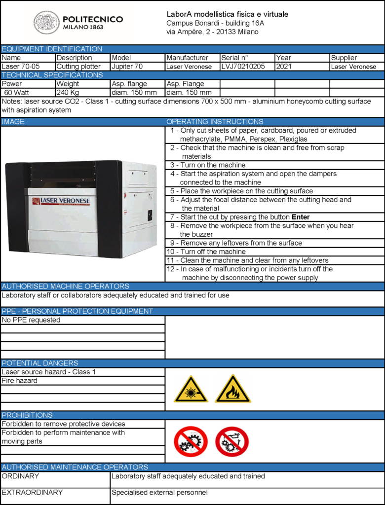
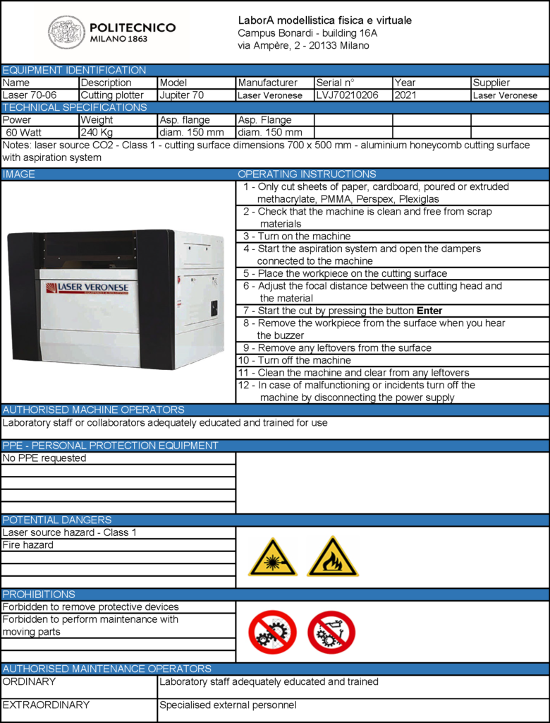
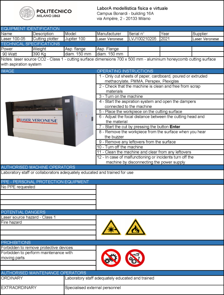
- machine scheets
- instruction manuals
- tutorial for the maintenance of the laser plotter – printable version
1. ordinary maintenance on a monthly basis
a. general cleaning of the inside of the plotter
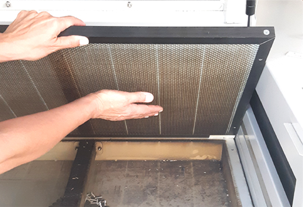
With the machine switched off, remove the honeycomb panel and with a vacuum cleaner remove all processing residues from the tank and the perimeter. If necessary, clean the surfaces with a sponge moistened with water. Before putting the honeycomb panel back in place, tap it lightly to remove residues inside.
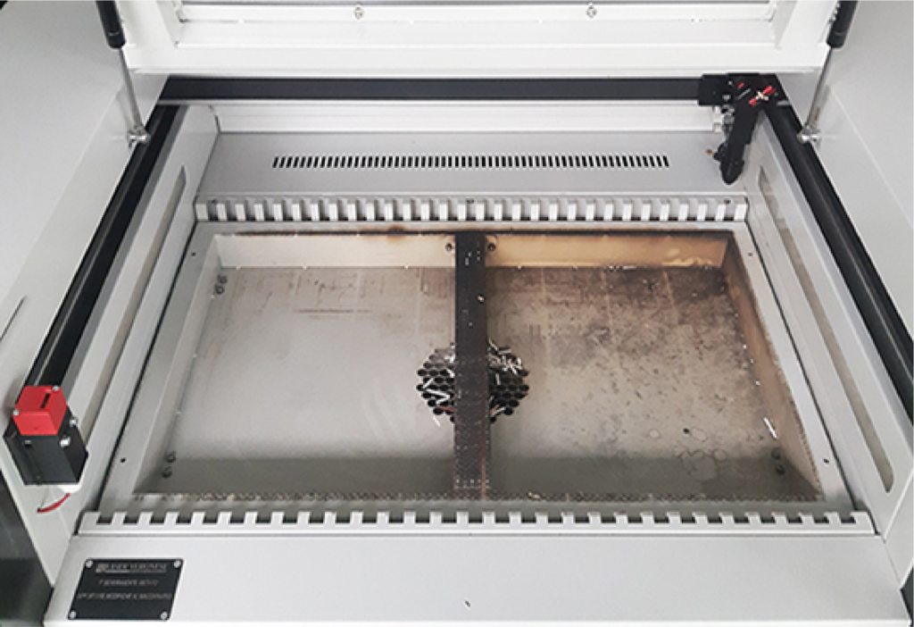
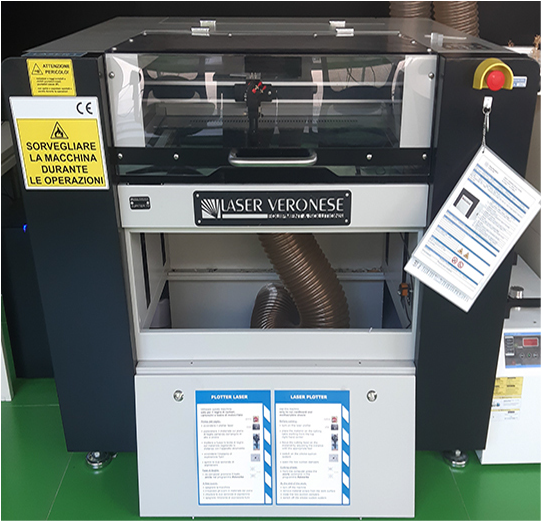
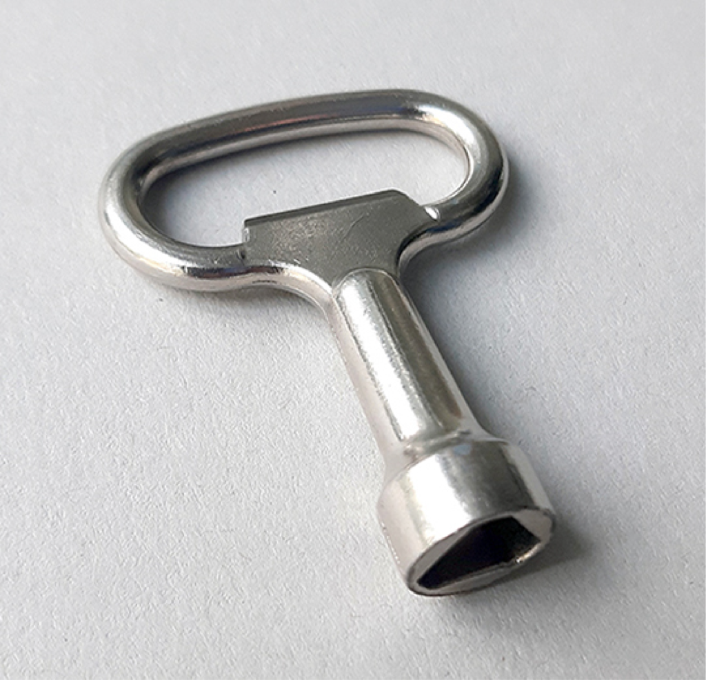
To complete the cleaning process, open the front door of the plotter with the specific key found in the CS1 drawer in the CNC Lab room and vacuum out any residue.
b. cleaning of the mirrors
Using wet wipes, which can be found in the CS1 drawer in the CNC Lab room, very gently clean the mirrors reflecting the laser beam, the first positioned to the left of the mobile bridge on which the laser head slides, and the second at the top of the head itself.
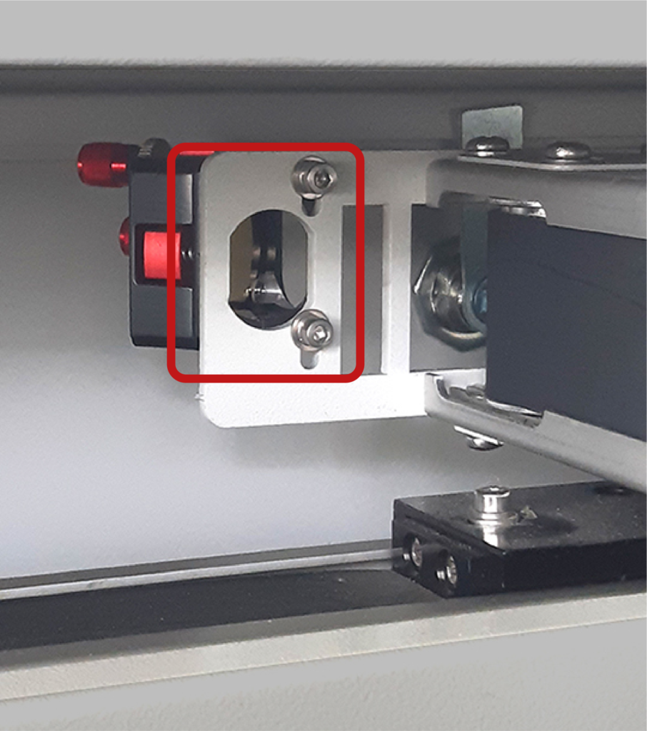
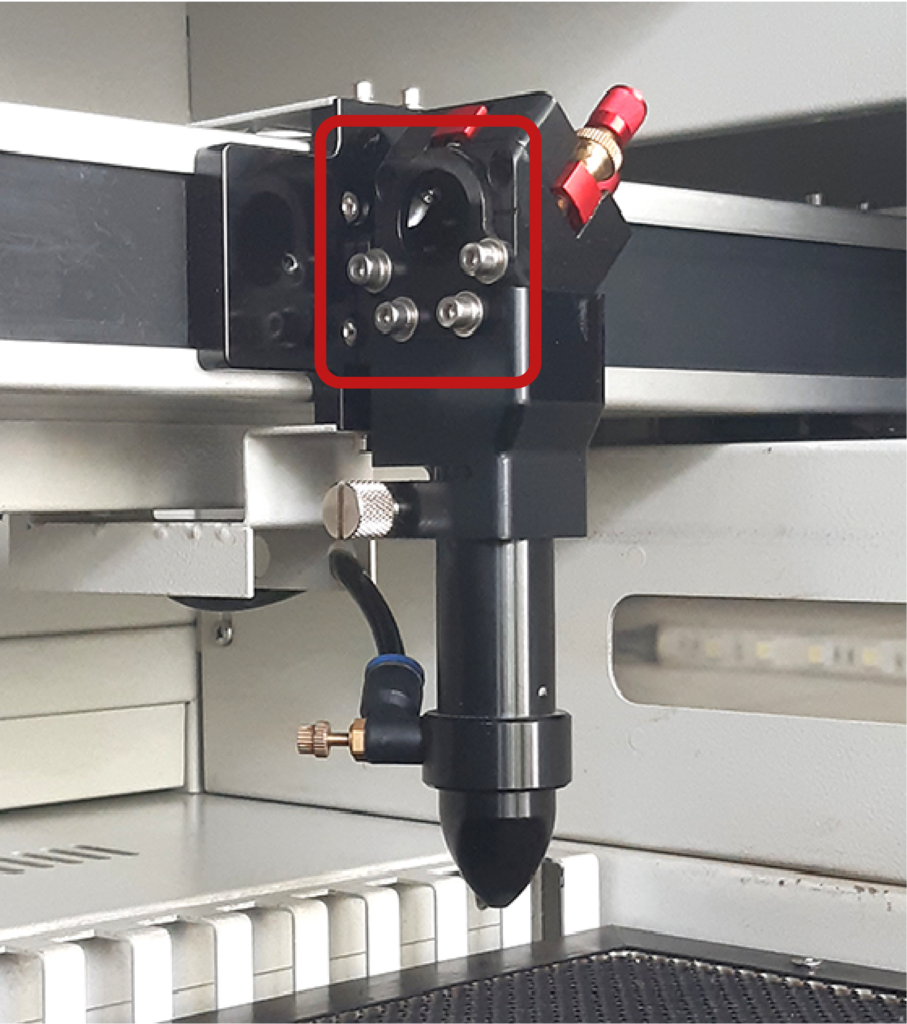
c. cleaning the focal lens
Since part of the laser head has to be removed, move it to a position that is convenient to reach. Lower the honeycomb panel by a couple of centimetres and switch off the laser plotter. Unhook the compressed air tube from the head’s stem: pull the tube while holding down the blue ring on the swivel connector.
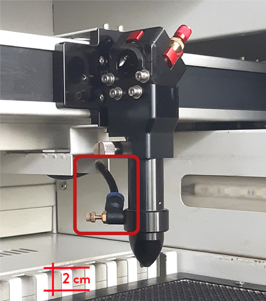
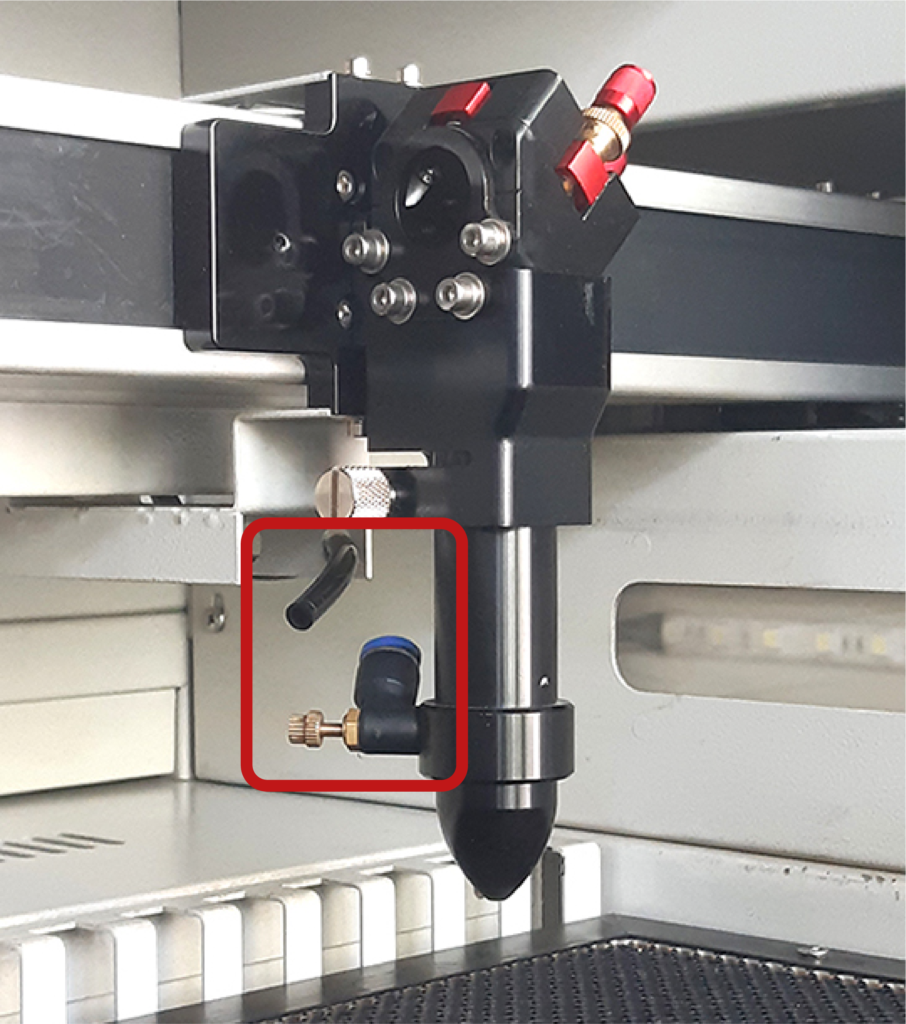
To remove the stem containing the lens, manually loosen screw A on the left side of the laser head.
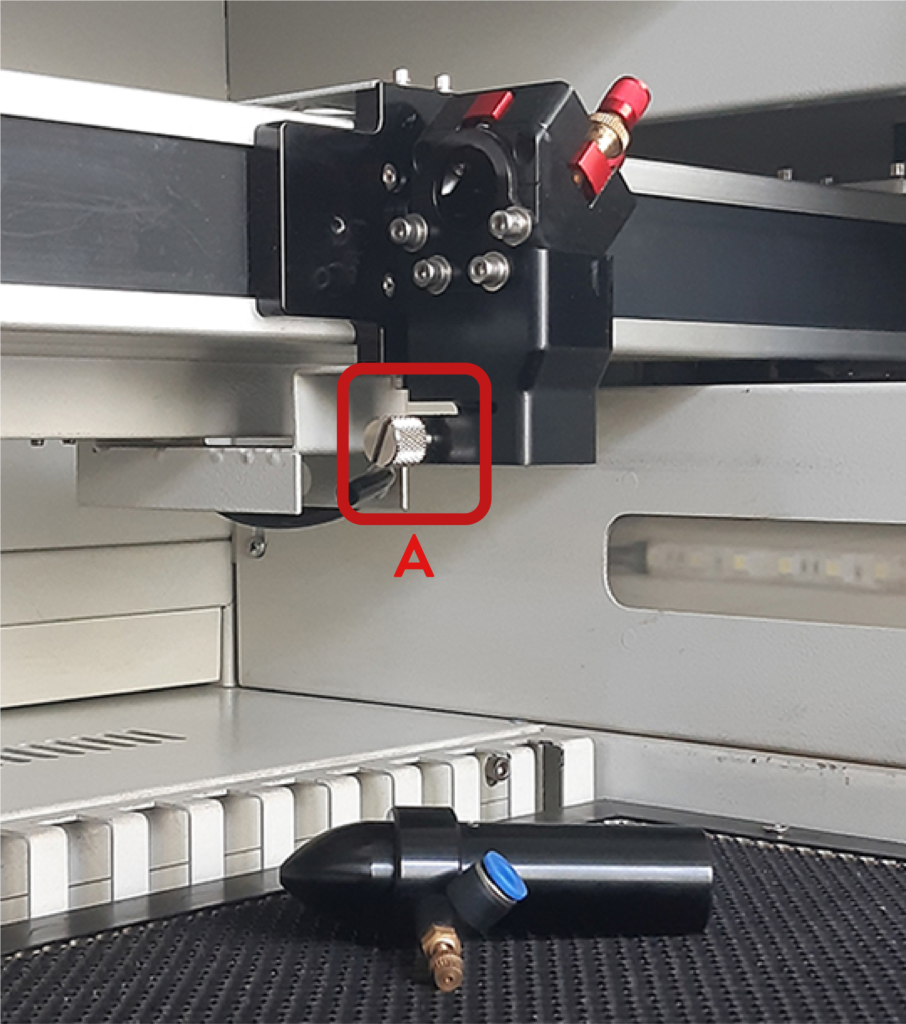
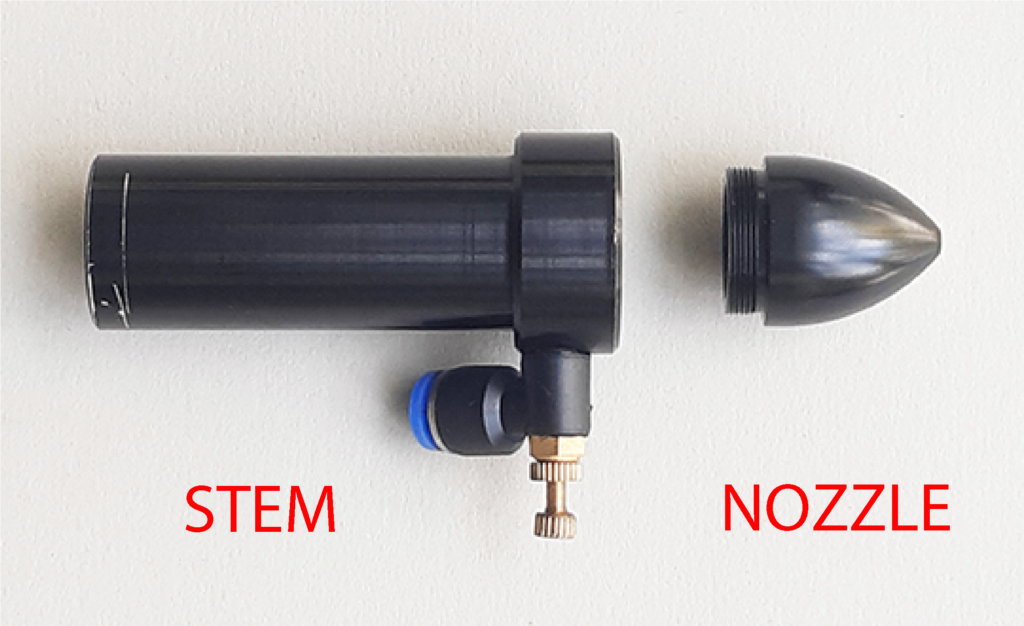
Unscrew the conical nozzle from the stem and wash it with soap and water.
Hold the stem and unscrew with the specific “T” tool, which is located in the CS1 drawer in the CNC Lab, the lower internal ring nut that holds the lens in place, then remove the lens.
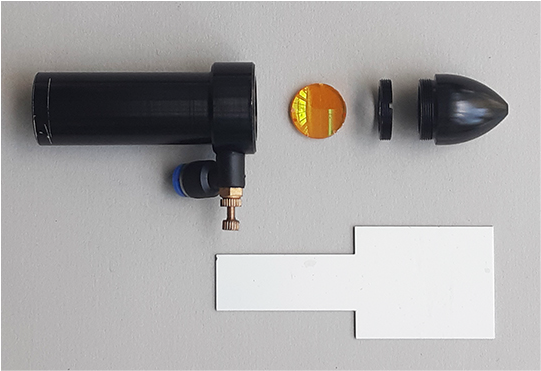
Clean it very gently using a wet wipe. Reposition the lens inside the stem, taking care that the convex part faces the nozzle. Before screwing on the ring nut, to check that the lens is not tipped, look inside the stem: if you see your image reflected as in a mirror, it means that the lens is positioned correctly.
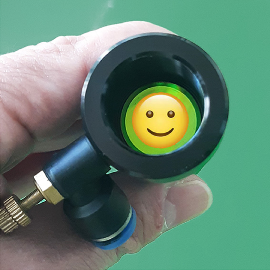
Screw back the nozzle onto the stem, insert the stem into the laser head and secure it by tightening screw A. Re-attach the compressed air tube by pushing it into the swivel connector.
At the end of this operation switch on the plotter to reset the plane to position Z = 0.
d. checking the distance of the honeycomb plane from the laser head to allow focusing correctly to obtain an even cut across the plane
Position the laser head near the top right-hand corner and adjust the focus with the spacer directly on the honeycomb plane. Check that the distance is the same near the other three corners and in the centre of the plane.
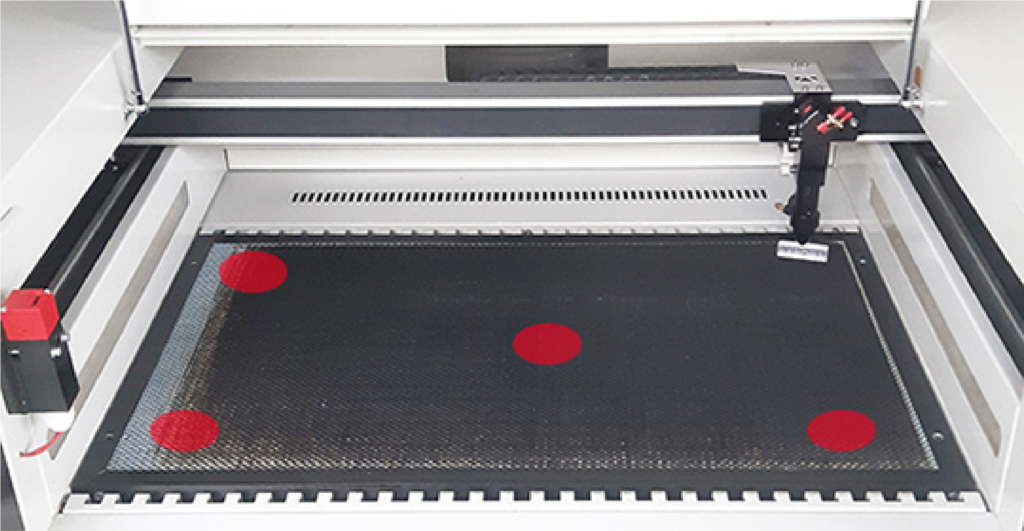
If there are different distances, only the height of the left side of the plane can be adjusted. Open the lower door on the left side of the laser with the specific key, which is located in the CS1 drawer unit in the CNC Lab.
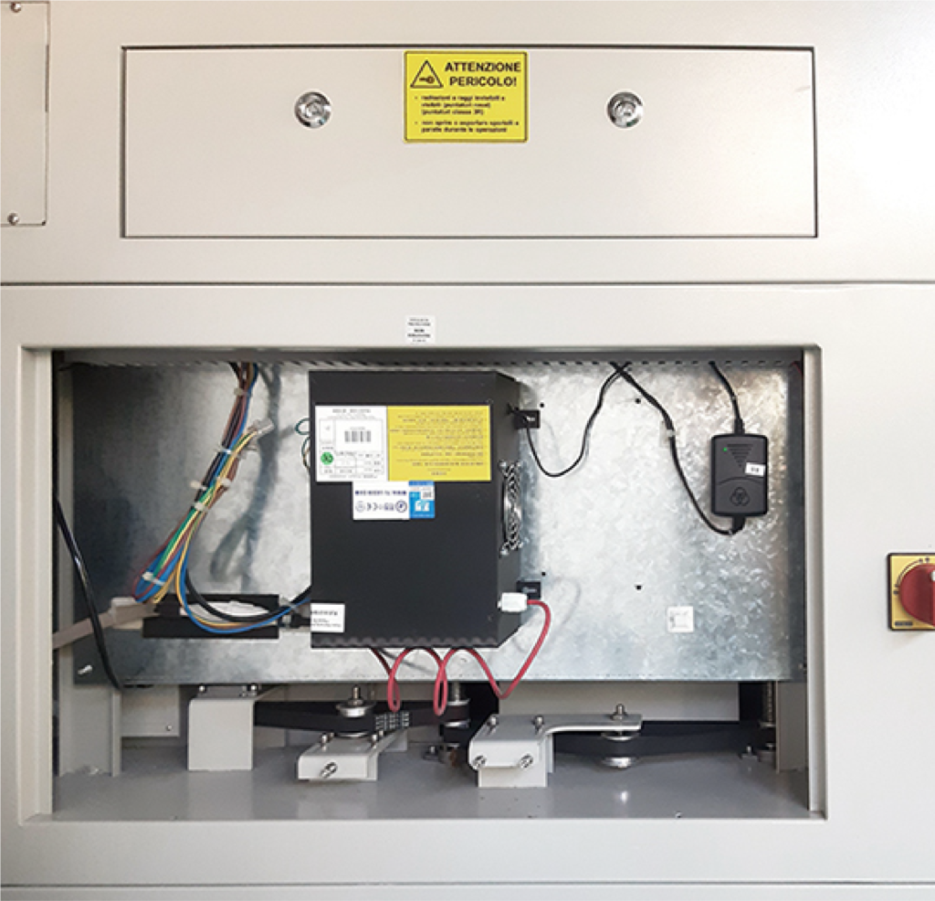

Move the drive belt located on the lower right-hand side:
the edge of the table is raised by pulling the belt to the right
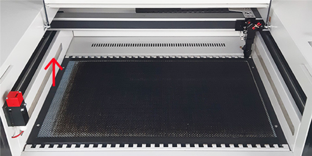
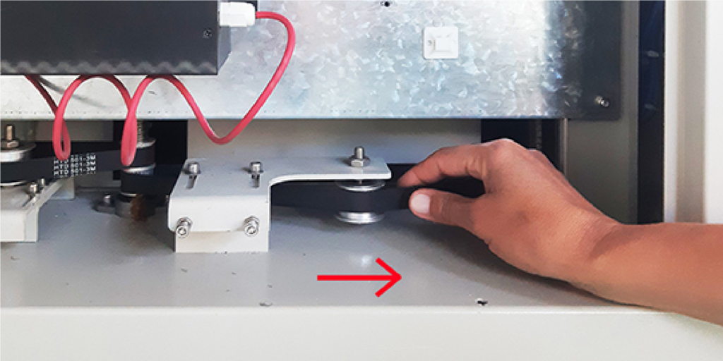
and lowers by pulling the belt to the left.
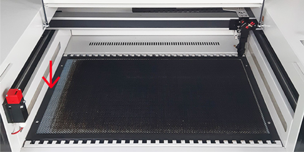
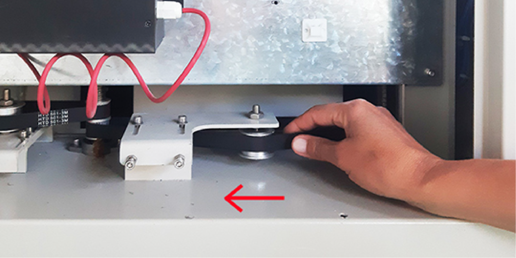
It is not possible to adjust the height of the front and rear sides of the table in the same way, but only by inserting cardboard shims under the frame of the table after raising it.
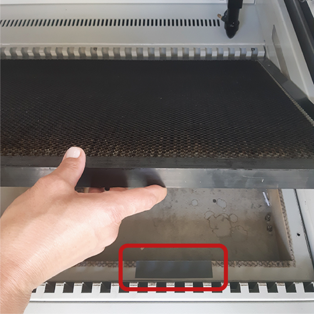
e. checking the focus to cut with the thinnest possible cutting line
It can happen that, due to vibrations, the lens has small movements within the stem. This can result in the optimum focus no longer matching the size of the spacer. To do this check, focus the laser head on a test cardboard. On the plotter’s control panel, press the pulse button to send a single laser pulse.
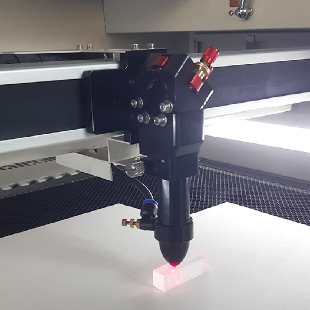
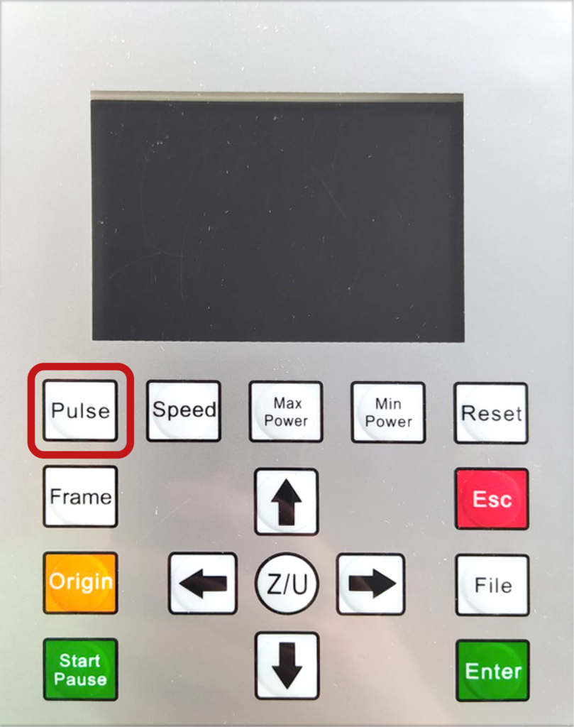
Try raising the stem by 1 or 2 mm, bring the head close to the test performed previously and press pulse again. Move the laser head slightly, reposition the focus with the spacer, then lower the stem by 1 or 2 mm and press pulse again. Compare the three burns and identify the thinnest one.
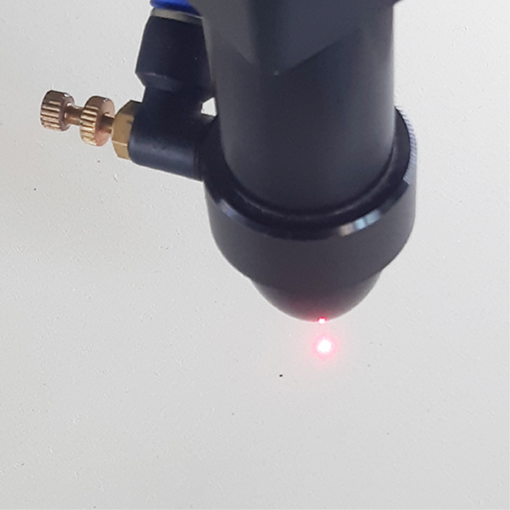
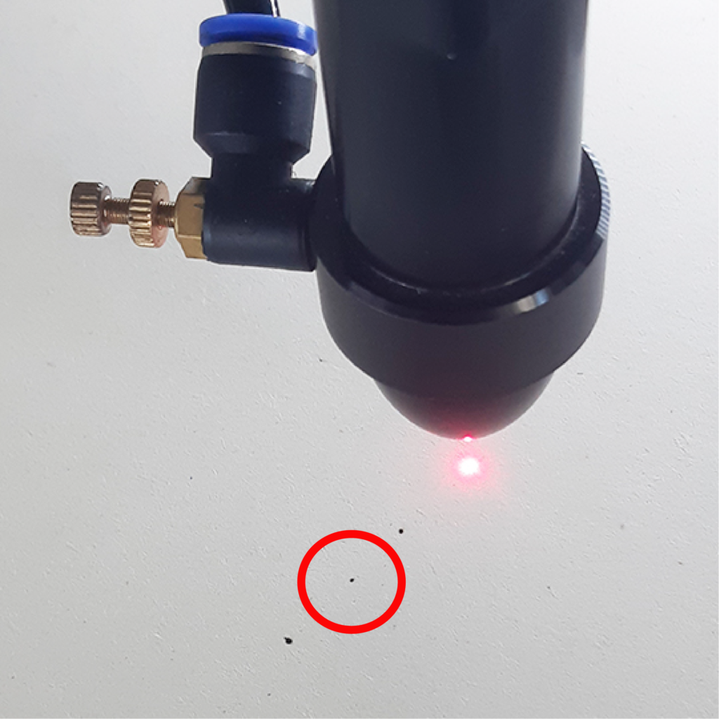
If the thinnest burn matches the adjustment made with the spacer, the lens is in the correct position for optimum focus. If, on the other hand, the thinnest burn is the one obtained by lowering the stem, the lens must be repositioned. Disassemble the lens (see chapter 1 – section c) and, in the case of Laser 3, unscrew the ring nut underneath on the inside of the stem to adapt the focus to the size of the spacer, bearing in mind that each full turn of this ring nut increases the focusing distance from the material by approximately one millimetre.
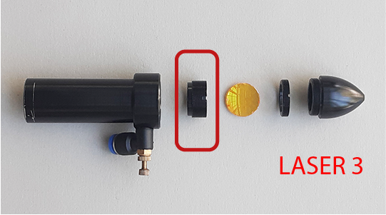
In the case of Lasers 1 and 2, the lens rests on a fixed support, so in order to increase the focusing distance from the plane, it is necessary to insert a gasket or ring nut of the correct thickness under the lens before reassembling it.
If the thinnest burn is the one obtained by raising the stem, in all three lasers, it is not possible to correct the height of focus, but it is necessary to acquire a suitably sized spacer.
f. checking the emergency button
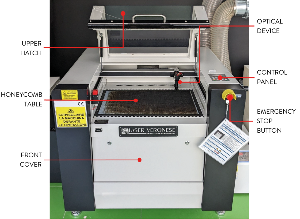
Start a cut with a test file and press the red emergency button to verify that the plotter shuts down by stopping all moving parts. Reset the plotter by turning the button clockwise, causing it to click outwards.
g. checking the shutdown sensors
Start a cut with a test file and check that when opening the top hatch, the laser head stops and the laser beam is switched off.
Also check that with the top hatch open, when starting a new cut, the head does not move and the laser beam is switched off.
h. checking the external chiller of the laser source
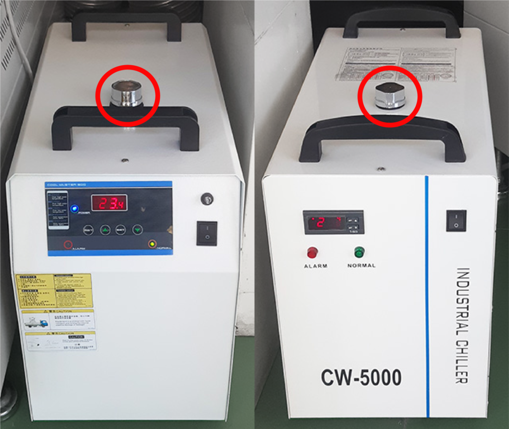
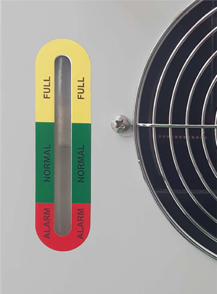
Check on the front display of the chiller that the operating temperature is below 30°. Also check the water level on the indicator at the rear of the chiller, which must be within the green area. If this is not the case, with the machine switched off, add distilled or demineralised water by unscrewing the silver cap at the top of the chiller.
2. ordinary maintenance every six months
a. lubrication of the drive belts and pulleys
To move the moving bridge and laser head along the X and Y axes, the plotter is equipped with 3 drive belts moved by pulleys. Two belts are located on the sides of the bridge to move it along the Y-axis and one on the bridge to move the head along the X-axis.
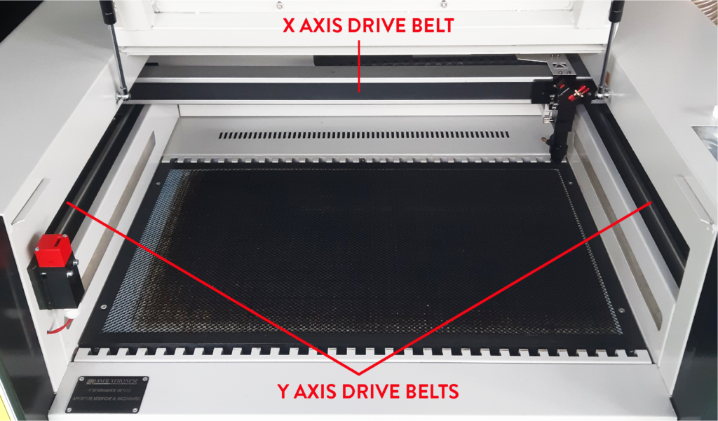
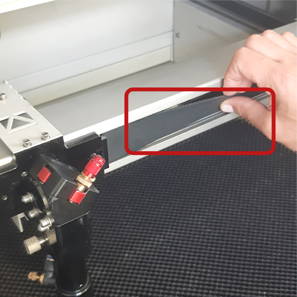
Using the spray lubricant found in the CS1 drawer in the CNC Lab, lubricate all three sliding seats of the belts to a length of 5 – 10 cm.
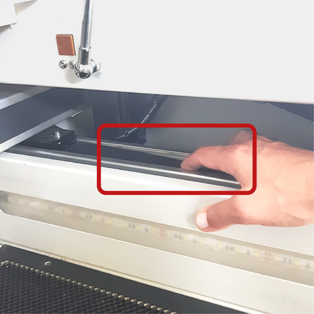
To lubricate the X-axis pulleys, open the upper door on the right-hand side of the plotter with the specific key, which can be found in the CS1 drawer unit in the CNC Lab.

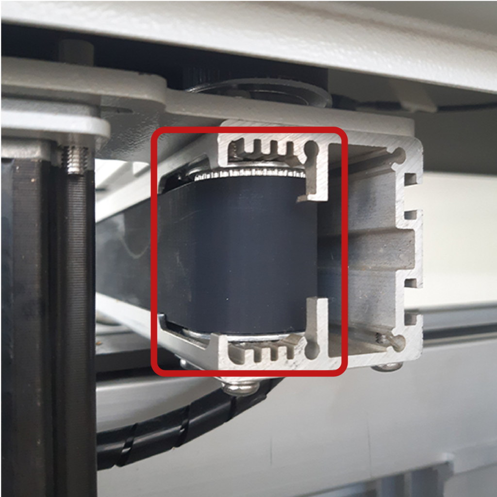
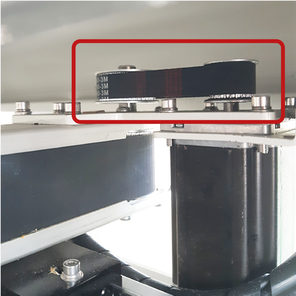
Lubricate the upper part of the large pulley and, from the worktop inside the plotter, also lubricate the two pulleys above the moving bridge.
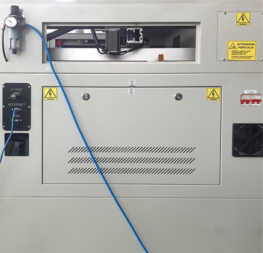
To lubricate the Y-axis movement pulleys, it is necessary to open the top door on the rear side of the plotter where the glass laser source is located. The pulleys are located at the end of the drive belts, one to the left and three to the right of the source.
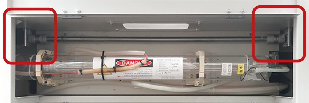
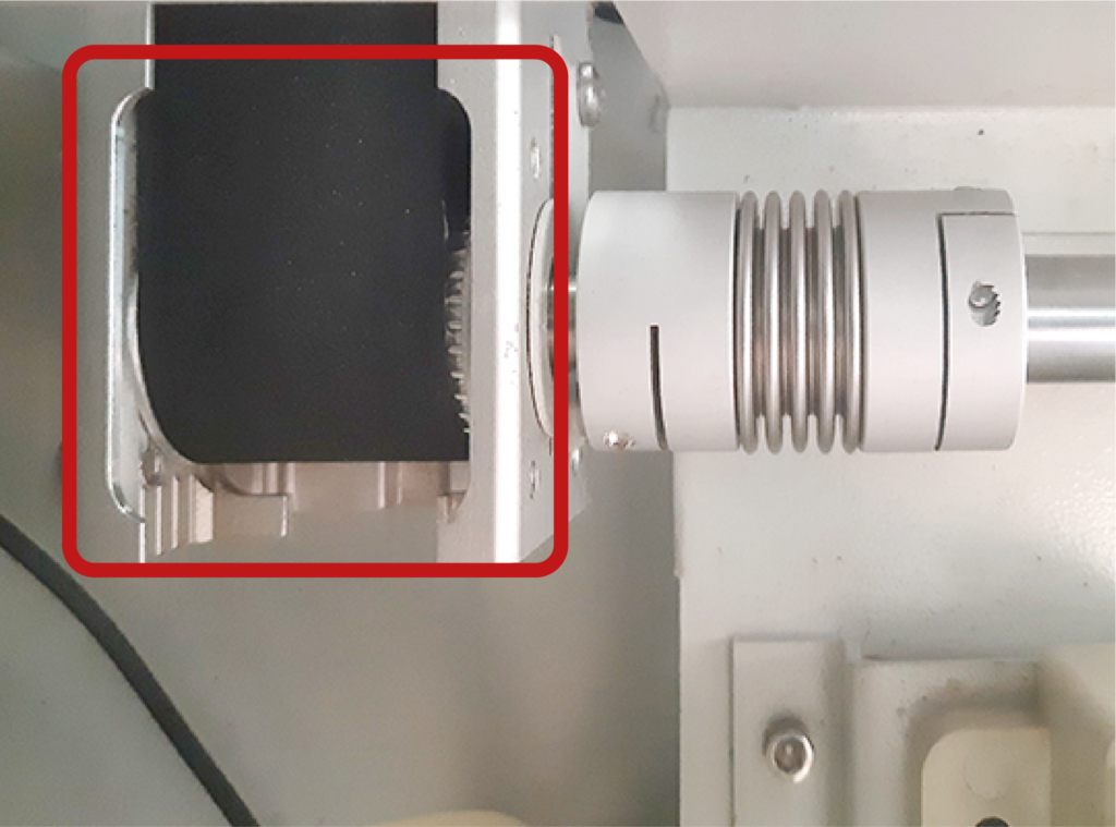
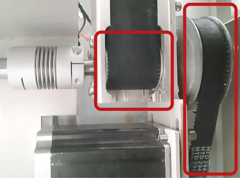
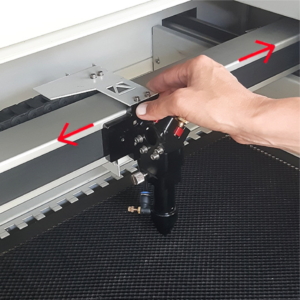
Once these lubrications are complete, close the doors again and, again with the machine switched off, manually move the laser head from right to left and the mobile bridge back and forth to spread the lubricant.

b. adjustment of the laser beam reflected on the moving bridge mirror
Place three overlapping pieces of paper tape over the opening containing the mirror in the laser head. Position the laser head near the top left corner of the honeycomb plane and press the pulse button on the control panel of the plotter.

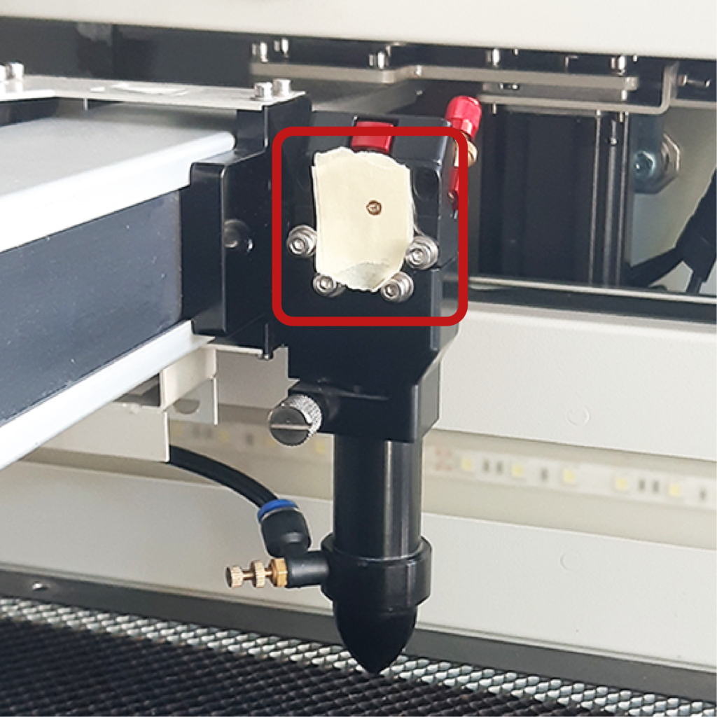
Move the head near the bottom right-hand corner and press pulse again. If the burns generated by the two laser pulses overlap into a single hole on the tape, the adjustment is correct. If they do not coincide and two holes appear, then the following adjustment is required: open the top door on the left-hand side of the machine, using the specific key located in the CS1 drawer in the CNC Lab.
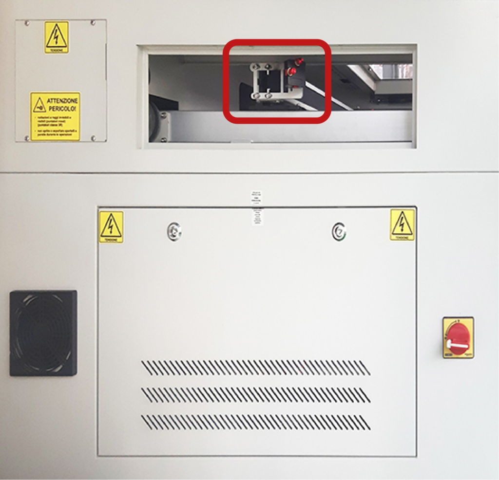

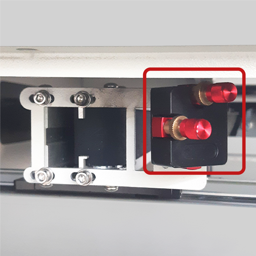
Unscrew the gold-colored retaining rings of the red screws and rotate the screws that adjust the mirror angle: the top screw Y moves the mirror by moving the laser beam vertically, the screw X horizontally. At the end of the adjustment tighten the rings.
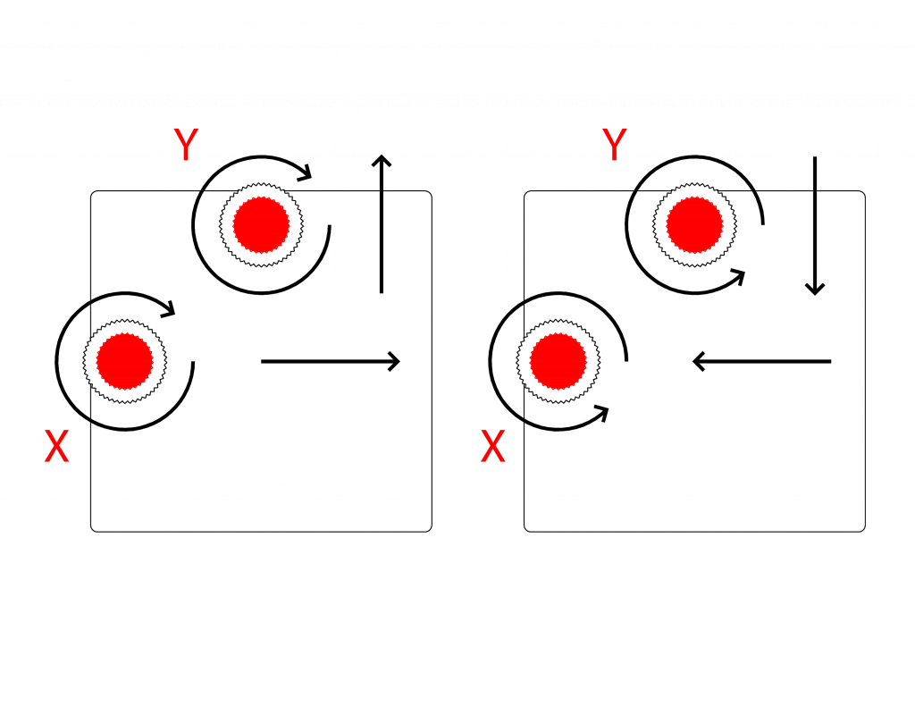
Carry out the previous checking procedure, replacing the triple layer of tape each time, until a single hole is obtained.
c. adjustment of the laser beam reflected by the laser head mirror
Place a piece of paper tape on the nozzle tip of the laser head and press to make it stick and mark the nozzle hole on the paper tape. Press the pulse button on the control panel of the plotter.
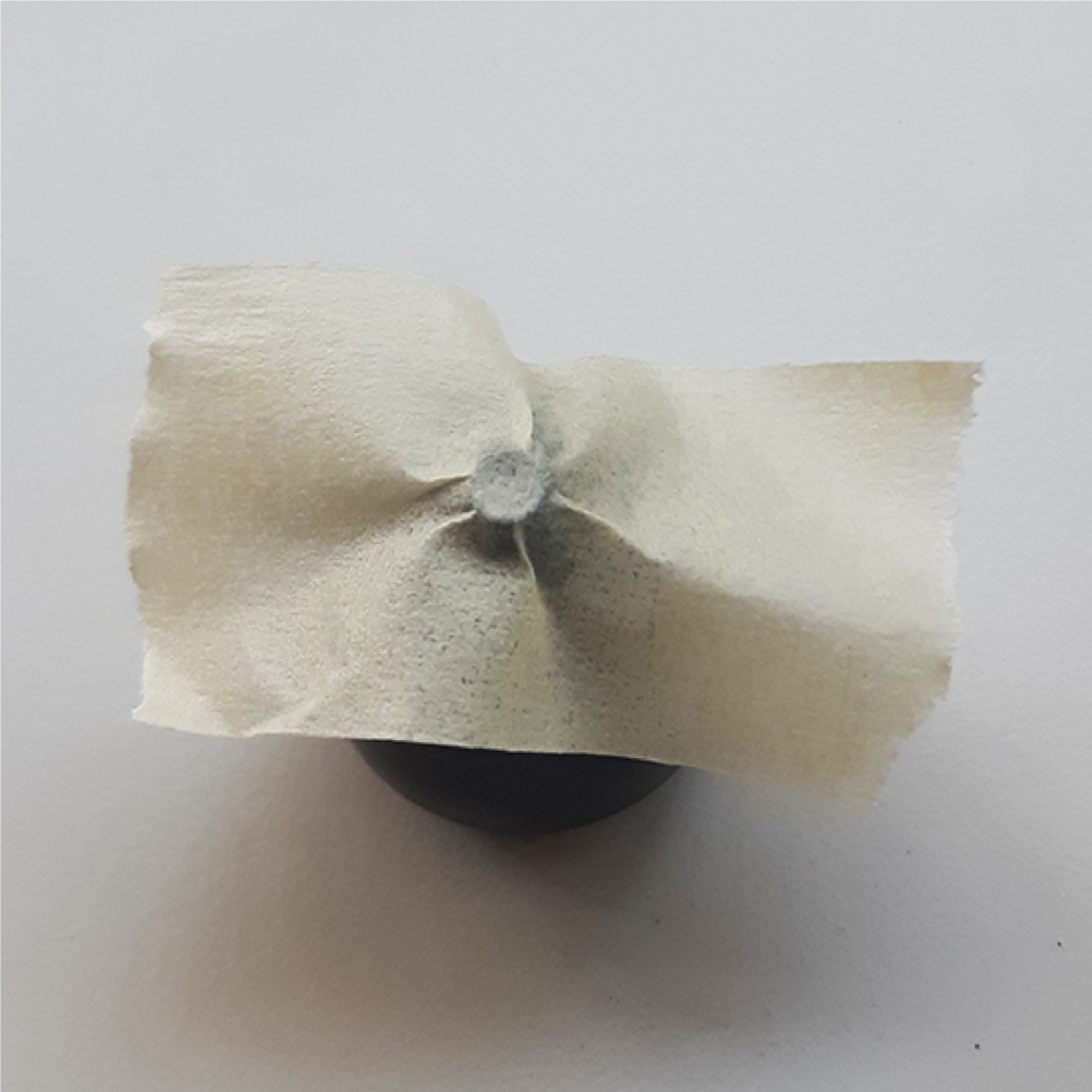

Remove the tape and check that the hole generated by the laser pulse is perfectly centred in relation to the nozzle hole mark. If so, the adjustment is correct.
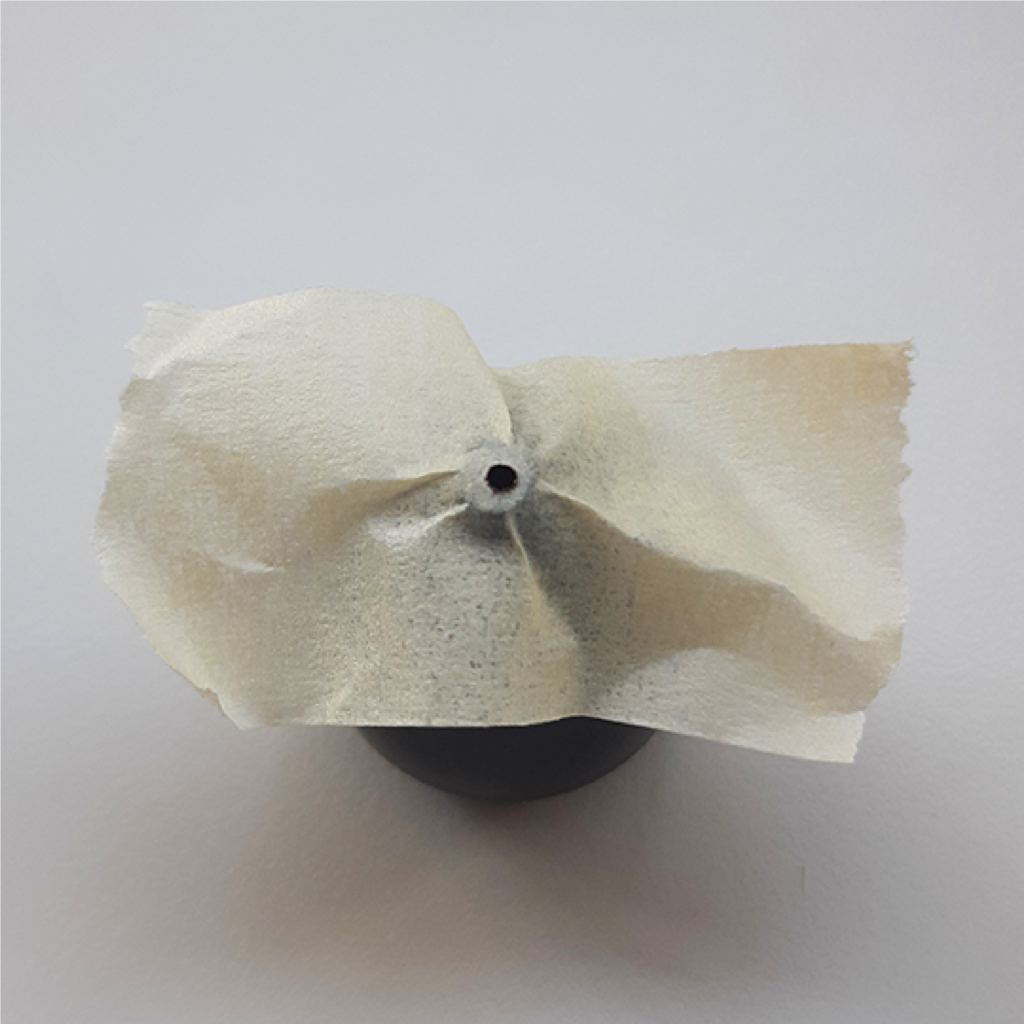
If the hole is off-centered, you need to make the following adjustment: unscrew the gold-colored retaining rings of the red screws on the cutting head and rotate these screws that adjust the angle of the mirror, the upper screw moves the mirror by moving the laser beam on the X axis of the honeycomb plane, the other on the Y axis; at the end of the adjustment tighten the rings.
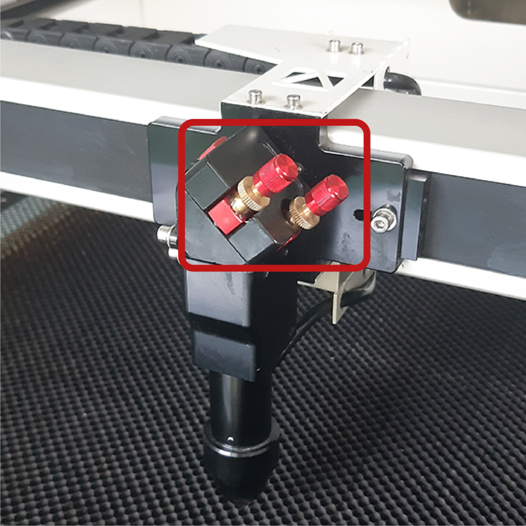
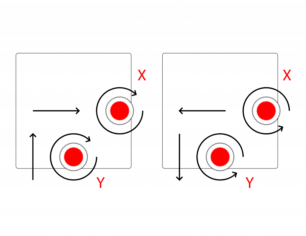
Carry out the previous checking procedure, replacing the tape each time, until the hole is centred in relation to the nozzle hole.
3. extraordinary maintenance by specialised personnel
ALL MAINTENANCE WORK NOT LISTED ABOVE AND THE REPLACEMENT OF COMPONENTS MAY ONLY BE CARRIED OUT BY SPECIALISED PERSONNEL.
a. manual modification of the “0” of absolute coordinates
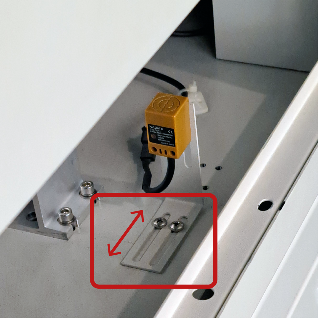
To change the absolute 0 on the y axis, open the top door on the right side of the machine, with the appropriate key that is located in the CS1 drawer of the CNC Lab room, unscrew the screws highlighted in the figure and move the limit sensor of the desired measurement.
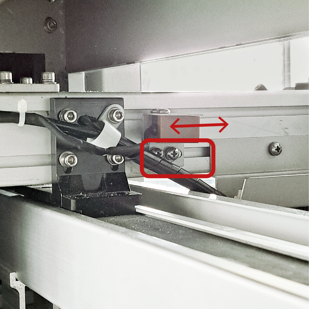
To change the absolute 0 on the x-axis, lift the front door, unscrew the screws highlighted in the figure and move the limit sensor of the desired measurement.
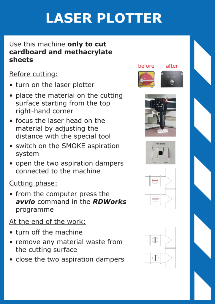
4. prohibitions and regulations

5. machine scheets
